IoT-LAB M3
| board ID | radio | OS support | deployment |
|---|---|---|---|
| m3 | 802.15.4 | RIOT Contiki-NG FreeRTOS | Lille 264 Grenoble 380 Saclay 12 Strasbourg 64 Paris 69 |
The IoT-LAB M3 board has been designed specially for the IoT-LAB testbed. It is based on a STM32 (ARM Cortex M3) micro-controller with an ATMEL radio interface in 2.4 GHz and 4 sensors. In terms of dimensions, it has a form factor (i.e. the CAD design of the embedded system) of 4 cm wide and 5 cm long.
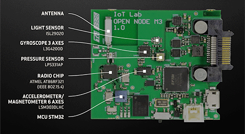
MCU
The IoT-LAB M3 board takes its name from the CPU it is equipped with: the Cortex M3 manufactured by ARM. The Cortex M3 is a 32-bit CPU set to a maximum speed of 72 MHz. The Cortex M3 is integrated into the STM32 MCU ( STM32F103REY) manufactured by STMicroelectronics, more commonly known as ST. The STM32 MCU is equipped with 64 KB of RAM and 256 KB of ROM. An example of a connected object employing the use of this same MCU is the Apple TV 4 remote control.
Radio chip
The radio chip AT86RF231 manufactured by Atmel (purchased in 2016 by Microchip) communicates over the 2.4 GHz ISM frequency band. This radio chip was designed to implement the MAC layer of the IEEE 802.15.4 standard, used by the Zigbee communication protocol, among others. The maximum bandwidth is 256 kbits/s. A small, 9 mm long ceramic antenna is welded onto the circuit. This type of radio technology falls into the “short-range” category, with maximum distances of 40/50 meters indoors and up to around 100 meters outdoors. Depending on these technical specifications, the radio chip consumes up to 14 mA when transmitting at maximum power. It is interconnected with the MCU on the SPI bus, enabling rapid data exchange. It is also connected to a GPIO port on the MCU in order to control the waking up of the radio chip in the event of it being set to standby mode.
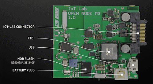
External NOR flash memory
A 128-Mbits external NOR flash memory (N25Q128A13E1240F) is connected to the MCU via the SPI bus in order to enable rapid data transfer. This memory is useful when it comes to storing data acquired by sensors while a program is running. Another use case is for OTA (Over The Air) updates to the MCU’s firmware. Some embedded operating systems partition this ROM memory in order to download and store different versions of the firmware.
Sensors
4 sensors connected to the MCU via the I2C bus are embedded into the IoT-LAB M3 board:
- the light sensor: this measures ambient light intensity in lux. ISL29020
- the pressure and temperature sensor: this measures atmospheric pressure in hPa. LPS331AP
- the accelerometer/magnetometer: this provides feedback on an object’s acceleration, and can be used to detect movement. By determining a threshold, it generates a change of state on one of the MCU’s digital inputs/outputs in order to create an interrupt, which can be used to bring the MCU out of standby mode. LSM303DLHC
- the gyroscope: this measures the orientation of an object in space and can be used, for example, to determine the orientation of the screen of a tablet or a smartphone. L3G4200D
LEDs
3 LEDs (red, green and orange) are connected to the MCU via the digital inputs/outputs. Usually, these are used to notify of MCU actions or application states. Even if you use the boards remotely, do not hesitate to use the LEDs as usual; it sometimes gives us an interesting visual feedback of users activity, like this one observed in 2017.
Power supply
The M3 node can be supplied in 3.3 V in two different ways:
- via the USB port
- via the external battery
In terms of the energy consumption of the different hardware devices, it should be noted that, at full power, the MCU consumes 14 mA, to which we must add the energy consumption of the other hardware devices. The radio chip, for example, consumes 14 mA when transmitting and 12 mA when receiving.
Typical use cases for constrained connected objects often require the use of a battery. In order to maximise the lifespan of objects, the energy-saving strategy employed involves switching the MCU and its various different components to standby mode once the object has finished processing. In the case of the STM32 MCU, consumption is reduced to 1 mA when in sleep mode, and remains below 1 μA in standby mode. The AT86RF231 radio chip supports the same type of features, with comparable energy savings.
Programming
You can reset, debug and program the STM32 on JTAG through the FTDI2232H connected to the USB. This component allows also a UART link to the STM32.
Architecture
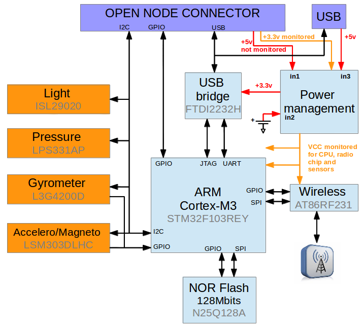
Complete schematics
* Note that the second UART on Open Node connector is not useable (wires RX an TX inversed).