IoT-LAB A8-M3
| board ID | radio | OS support | deployment |
|---|---|---|---|
| a8 | 802.15.4 | Yocto | Grenoble 228 Saclay 115 Strasbourg 14 Paris 62 |
The IoT-LAB A8-M3 board is based on a TI SITARA AM3505 which is a high-performance ARM Cortex-A8 microprocessor. Its 600 MHz clock speed enable to run an embedded Linux or Android. It enables to run applications used in advanced devices such as set-top box or smartphone/tablet in order to concentrate sensors information.
MCU
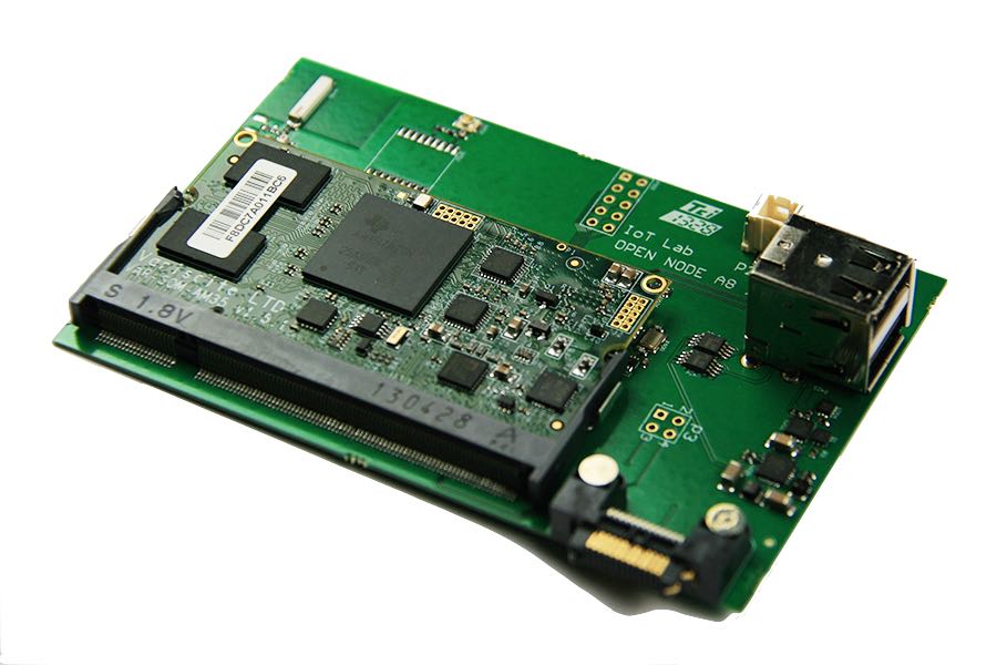
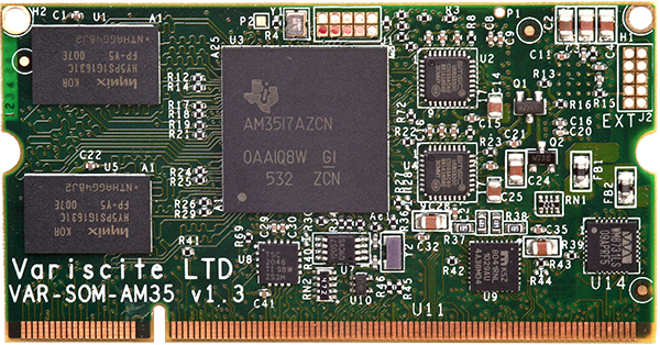
The IoT-LAB A8-M3 board takes its name from the CPU it is equipped with: the Cortex A8, manufactured by ARM. Based on Armv7 architecture, the Cortex A8 is a 32-bit CPU set to a frequency of 600 MHz, consuming less than 300 mW. The TI SITARA AM3505 processor, providing the Cortex A8, is integrated into the VAR-SOM-AM35, a low-power and high performance System-on-module made by Variscite. Like an MCU, it is equipped with all the components it needs to be run, but produced into a DDR2 SODIMM connector form factor circuit board designed specifically for industrial applications.
This industrial board is inserted into a circuit equipped with all required external components.
The final assembly has 256 MB of RAM. All these technical characteristics put the IoT-LAB A8-M3 board in the user terminal (e.g. smartphones) or gateway (e.g. home automation systems) class of objects.
M3 co-microcontroller
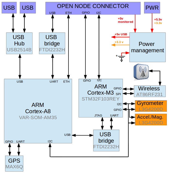
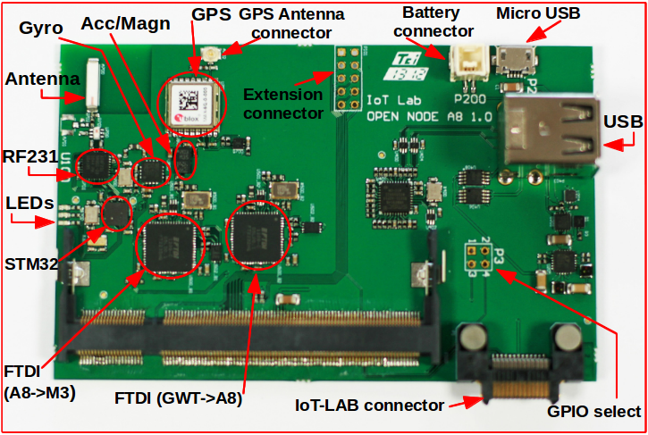
The IoT-LAB A8-M3 embed a clone of the IoT-LAB M3 object. As a result, it features the same sensors/actuators, as well as the same radio chip, enabling it to communicate wirelessly with other 802.15.4 objects within radio range. The M3 is linked to the A8 via the I2C data bus and the GPIO inputs/outputs. This M3 co-microcontroller can be programmed from the A8 through a USB/FTDI component (see Programming).
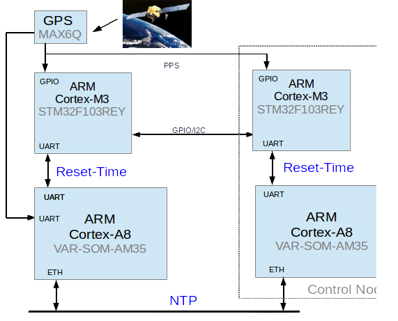
GPS
A sub-set of the IoT-LAB A8-M3 boards are equipped with a MAX-6Q GPS module as extra option. The GPS signal reception allows using the GPS clock as a precise time synchronization mechanism under the microsecond. This feature allows to precisely draw the events timeline between boards equipped with GPS.
The M3 control node and the M3 co-microcontroller can read by interruption the GPS PPS (Pulse Per Second) signal. This PPS acquisition can be used to counterbalance the M3 clock drift very accurately each second.
This local precise timer can be initialized by the A8 NTP time (Network Time Protocol) through the UART link, or by using the control node unix time through the I2C link.
Current deployment:
- 165 nodes on Saclay site (all open-a8 nodes)
- 32 nodes on Grenoble site (open-a8 list)
Both sites are equipped with an internal repeater GPS antenna. Hanger Re-Radiating Kit - HNRRKIT (Used in Grenoble)
See the GPS Synced Sniffer tutorial for an example using GPS of IoT-LAB A8-M3 board to precisely time sniffed radio packets.
Ethernet
The IoT-LAB A8-M3 board features an Ethernet interface, enabling it to connect to a LAN and to communicate with the internet. The boards are only accessible by SSH in IPV4 via the SSH frontend and in IPV6 from the Internet.
Power supply
Concerning the power consumption, only the global + 5 volts is monitored.
Programming
The IoT-LAB A8-M3 board run an embedded Linux that is built with Yocto. You can reset, debug and program the M3 co-microcontroller (i.e. STM32) on JTAG through the FTDI2232H connected to the USB. We provide in the Linux image scripts to perform these operations (i.e. iotlab_flash|reset|debug). This component allows also a UART link to the STM32 (i.e. /dev/iotlab/ttyA8_M3 with baudrate 500000)
Architecture